Tesseract Setup Wizard
Overview
The Tesseract Setup Wizard is a GUI that is designed to help you generate a Semantic Robot Description Format file (SRDF). This file defines your robot’s:
allowed collision matrix
kinematics groups
user defined joint states
user defined tool center points (TCPs)
OPW kinematics parameters
Getting Started
The Tesseract Setup Wizard is part of the Tesseract Ignition snap package.
You can install this package by using the following command:
sudo snap install tesseract-ignition
Step 1: Start
Note
If you are using ROS, make sure you source your workspace before launching the Tesseract Setup Wizard
Launch the Tesseract Setup Wizard with the following command:
tesseract-ignition.tesseract-setup-wizard
Note
The Tesseract Setup Wizard contains a toolbar with pages for each component of the SRDF file. To navigate to different pages, you must click on the dark gray background of the tool bar, hold, and drag you mouse left or right.
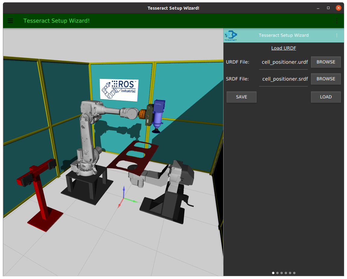
Step 2: Load URDF and SRDF
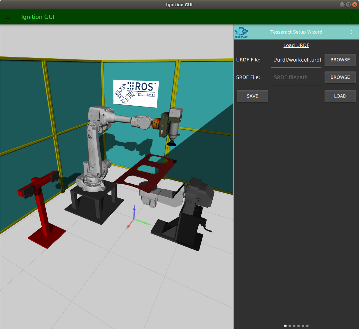
To use the Tesseract Setup Wizard and create/edit a SRDF file, we’ll first need to load in your URDF file. If you’d like to edit an existing SRDF, you may also load that in as well.
To load in your URDF file:
Click the BROWSE button to the right of the URDF File field.
Find and select your URDF file.
If you would like to edit an existing SRDF file:
Click the BROWSE button to the right of the SRDF File field.
Find and select you SRDF file.
Once you have selected your URDF file (required) and SRDF file (not required):
Click LOAD to load your model into the setup wizard.
At this point, you should see your model appear in the workspace to the left of the toolbar.
If your model did not appear, check the terminal to see error messages that will help you debug the issue.
Click, hold, and drag left to move to the next page.
Step 3: Generate/Edit Allowed Collision Matrix
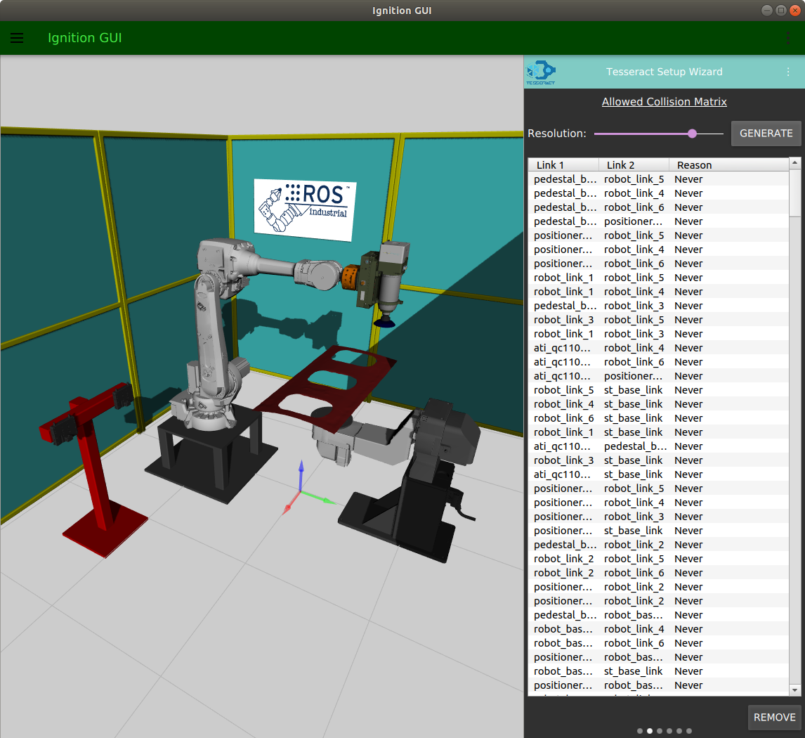
The allowed collision matrix specifies which links don’t need to be checked for collisions. Links that are adjacent to each other or are never in collision should be ignored by the Tesseract Collision Manager.
Note
If you loaded in an existing SRDF file, the table should already be populated with your allowed collision matrix.
To generate an allowed collision matrix:
Click GENERATE. After a couple seconds you should see the table populate with your default collision matrix.
Inspect your collision matrix and ensure that there are no link pairs that should not be disabled for collision checking.
If you would like to remove a link pair (enabling it for collision checking) select the row in the table corresponding to the link pair, and click REMOVE.
Click, hold, and drag left to move to the next page.
Step 4: Create/Edit Kinematics Groups
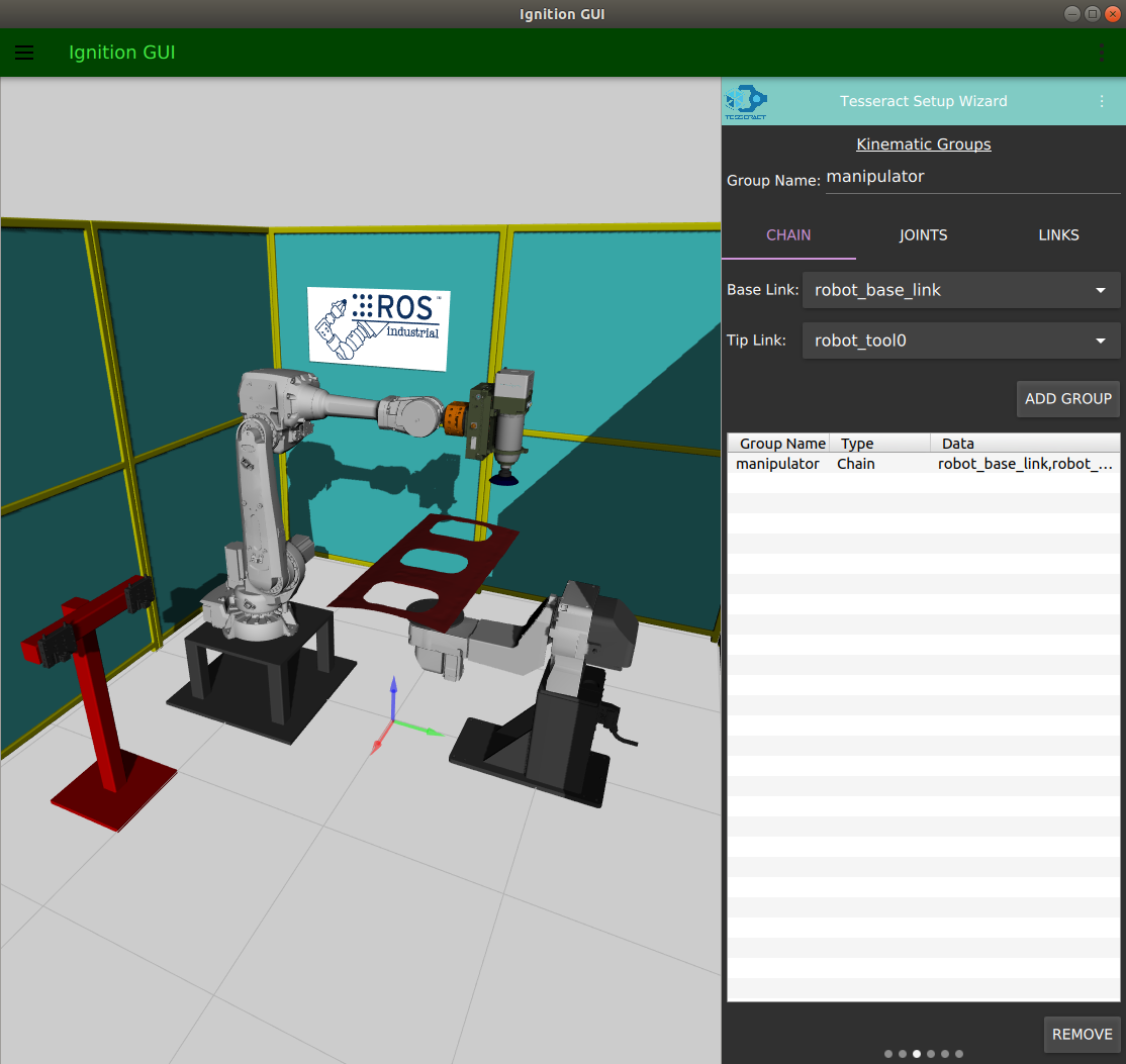
A kinematics group specifies a group of links that belong to a specific part of your robot. Usually, you’ll want to specify the chain of links that represent the arm and will be used for motion planning.
A kinematics group can be specified in three ways:
By selecting a chain of links
By selecting each joint in the group
By selecting each link in the group
First, enter a name for your kinematics group in the Group Name field.
Method 1: Select Chain of Links
Specifying a chain is the most common way to specify kinematics group.
To do this:
Click the CHAIN tab.
Click the Base Link drop down box.
Select the link that represents the first link in your chain (usually this is named something like base_link).
Click the Tip Link drop down box.
Select the link that represents the end of your chain (usually this is named something link tool0 or tcp).
Click ADD GROUP to add the chain to your list of kinematics groups.
Method 2: Select All Joints
You can also specify a kinematics group by specifying each joint in the group. To do this:
Click the JOINTS tab.
Click the Joint Names drop down box.
Select a joint to add to the group.
Click ADD to add the joint to the group.
Repeat steps 1-4 for each joint.
If you need to remove a joint, select the joint in the list and click REMOVE
Once you have added all joints to your group, click ADD GROUP.
Method 3: Select All Links
You can also specify a kinematics group by specifying each link in the group. To do this:
Click the LINKS tab.
Click the Link Names drop down box.
Select a link to add to the group.
Click ADD to add the link to the group.
Repeat the last three steps for each link.
If you need to remove a link, select the link in the list and click REMOVE
Once you have added all links for your group, click ADD GROUP.
Removing a Group
To remove a group, select the group in the table and click REMOVE (at the bottom of the tool bar).
Click, hold, and drag left to move to the next page.
Step 5: Create/Edit Joint States
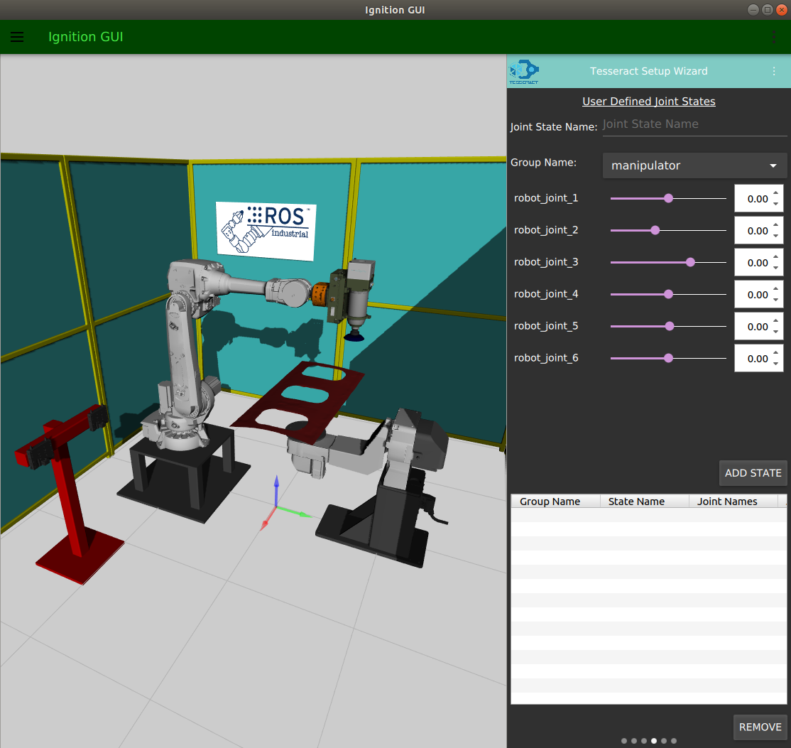
The User Defined Joint States page allows you to define different poses for your robot. For example, it is often useful to create a joint state called Home which contains the joint values for the starting/ending state of your robot.
To define a joint state:
Enter a name for your joint state in the Joint State Name field.
Select the kinematic group that you would like to use from the Group Name drop down box.
After selecting a group name, a value field for each joint should appear bellow the Group Name drop down box. For each joint, select the value you’d like to set for the robot’s position.
Once each joint value is set, click ADD STATE.
To remove a joint state:
Select the joint state from the table.
Click REMOVE.
Click, hold, and drag left to move to the next page.
Step 6: Create/Edit TCPs
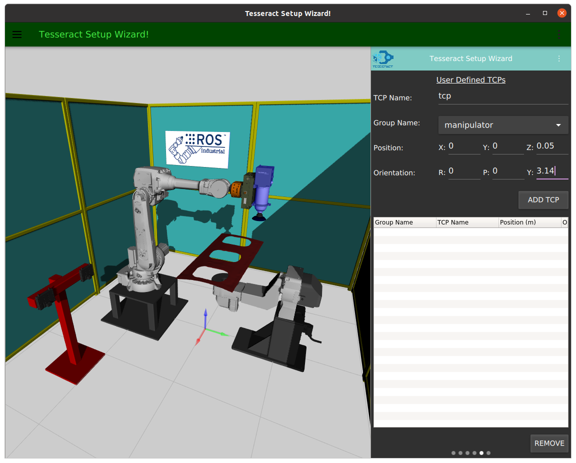
The User Defined TCPs page allows you to define Tool Center Points for your kinematic groups.
To define a TCP:
Enter a name for your TCP in the TCP Name field.
Select the kinematic group that you would like to use from the Group Name drop down box.
In the Position fields enter the X, Y, and Z positions of the TCP in reference to the last link in your kinematics group.
In the Orientation fields enter the Roll (R), Pitch (P), and Yaw (Y) of the TCP in reference to the last link in your kinematics group.
Click ADD TCP.
To remove a TCP:
Select the TCP from the table
Click REMOVE.
Click, hold, and drag left to move to the next page.
Step 7: Setting OPW Parameters
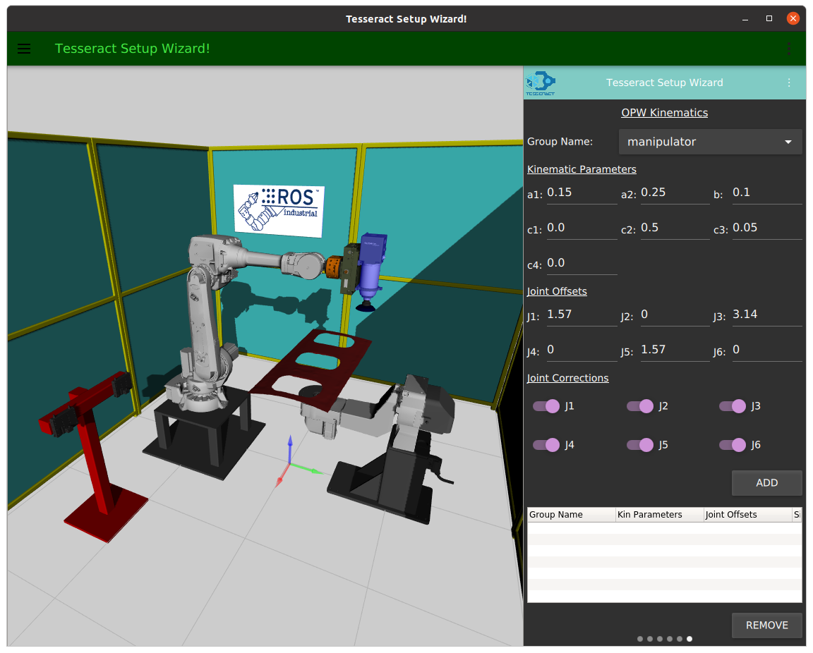
OPW is an efficient inverse kinematics solver for robots with parallel bases and spherical wrists. This algorithm requires 7 measurements from the robot’s specification sheet to be defined here. These values will be stored in the SRDF and used by the OPW solver.
To define your robot’s OPW parameters:
Use the following diagram to determine each parameter
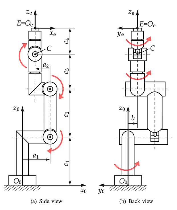
Enter each value in it’s respective field.
For more details on the OPW algorithm, visit the opw_kinematics github repository.
Click, hold, and drag left to move to the next page.
Step 8: Saving the SRDF File
Settings for the allowed collision matrix, kinematics groups, joint states, tcp values, and OPW parameters are all stored in a Semantic Robot Description Format file (SRDF).
To save your SRDF file:
Scroll back to the left most page where you originally loaded your URDF file.
Click SAVE and select a file and location to save the SRDF to.